文章目录[隐藏]
AIR-SARShip-1.0遥感目标检测数据集图像裁剪
数据介绍
高分辨率SAR舰船检测数据集-1.0(AIR-SARShip-1.0)首批发布31幅图像,图像分辨率包括1m和3m,成像模式包括聚束式和条带式,极化方式为单极化,场景类型包含港口、岛礁、不同等级海况的海面,目标覆盖运输船、油船、渔船等十余类近千艘舰船。
图像尺寸约为3000×3000像素,图像格式为Tiff、单通道、8/16位图像深度,标注文件提供相应图像的长宽尺寸、标注目标的类别以及标注矩形框的位置。完整介绍以及数据下载途径详见雷达学报的这个连接
因为图像比较大,因此我们需要对1.0版本的图像进行裁剪,这里的AIR-SARShip-1.0数据集是PASCAL VOC标注格式,图像本身是16位深度,裁剪后也保留这两点,裁剪的代码稍加改动也适用于其他标注类型为矩形框的检测数据集。

裁剪工作准备
- 准备数据:
下载数据集,将其解压之后按照标注文件(扩展名为.xml)和图像分别整理到annotations和images两个文件里,把这两个文件夹放在一个目录下; - 准备所需依赖包;
opencv,numpy,matplotlab,lxml - 明确你都要把数据存在哪个文件夹里,确保这个文件夹存在;
- 新建一个.py文件,检查没啥问题之后就可以直接用代码了。
代码及注释
这里先说明一下,代码是python写的,代码里有一部分是裁剪图像的可视化,设计这个是为了方便自己检查是否裁剪对了,如果你的数据集量比较大,那检查一次之后还是把这部分注释掉吧,一张一张多麻烦啊;
另外,关于裁剪的路径和参数设置,都在函数外面的代码的最下面写着,过滤零像素过多的图像的阈值在相关函数里面写着,按照需求自己改改吼~
import os
import cv2
import xml.etree.ElementTree as ET
from lxml import etree, objectify
import numpy as np
import matplotlib.pyplot as plt


def _bbox_area_computer(bbox):
    width = bbox[1] - bbox[0]
    height = bbox[3] - bbox[2]
    return width * height


def read_annotation_xml(xml_file):
    tree = ET.parse(xml_file)

    imageid = int((tree.find('filename').text).replace('.tiff', ''))

    size = tree.find('size')
    width = int(size.find('width').tail)
    height = int(size.find('height').tail)
    image_size = [width, height]

    resolution = tree.find('resolution').text
    sensor = tree.find('sensor').text
    source_info = [resolution, sensor]
    objs = tree.findall('object')

    small_object = 0
    middle_object = 0
    large_object = 0

    bboxes = []

    for obj in objs:
        bndbox = obj.find('bndbox')
        [xmin, xmax, ymin, ymax] = [
            int(bndbox.find('xmin').text),
            int(bndbox.find('xmax').text),
            int(bndbox.find('ymin').text),
            int(bndbox.find('ymax').text)
        ]
        if xmin < 0:
            xmin = 0
        if ymin < 0:
            ymin = 0
        bbox = [xmin, xmax, ymin, ymax]
        bboxes.append(bbox)

        area_of_bbox = _bbox_area_computer(bbox)

        if area_of_bbox <= 32 * 32:
            small_object += 1
        elif area_of_bbox <= 64 * 64:
            middle_object += 1
        else:
            large_object += 1

    print(' Number of small objects:{0}'.format(small_object))
    print(' Number of middle objects:{0}'.format(middle_object))
    print(' Number of large objects:{0}'.format(large_object))
    return imageid, image_size, source_info, bboxes


def two_points_belong_to_the_orignial_bbox_area(bbox, temp_bbox):
    if (temp_bbox[0] - bbox[0]) * (temp_bbox[0] - bbox[1]) <= 0 and (temp_bbox[2] - bbox[2]) * (
            temp_bbox[2] - bbox[3]) <= 0 and (temp_bbox[1] - bbox[0]) * (temp_bbox[1] - bbox[1]) <= 0 and (
            temp_bbox[3] - bbox[2]) * (temp_bbox[3] - bbox[3]) <= 0:
        return True
    else:
        return False

def do_filter_to_inappropriate_data(subImage, threshold=16384): #if there are too many zero pixel in the image then return True, you can adjust the threshold to what you want
    zero_pixel_num = (subImage.reshape(-1,1)[:,0]==0).sum()
    if zero_pixel_num >= threshold:
        return True


def add_gt(img_data, bboxes):
    colors = (0, 0, 255)
    for bbox in bboxes:
        cv2.rectangle(img_data, (bbox[0], bbox[2]), (bbox[1], bbox[3]), colors, 5)
    return img_data


def tiff_image_visualization(img_data):
    img_data = 255 * (np.log2(img_data + 1) / 16)
    img_data = img_data.astype(np.uint8)
    return img_data

def save_to_xml(xml_path, Image_shape, source_info, sub_bboxes, img_name):
    E = objectify.ElementMaker(annotate=False)
    anno_tree = E.annotation(
        E.folder('AIR-SARShip-1.0-SUB'),
        E.filename(img_name),
        E.source(
            E.database('AIRSAR'),
            E.resolution(source_info[0]),
            E.sensor(source_info[1]),
        ),
        E.size(
            E.width(Image_shape[1]),
            E.height(Image_shape[0]),
            E.depth(Image_shape[2])
        ),
        E.segmented(0),
    )

    for bbox in sub_bboxes:
        E2 = objectify.ElementMaker(annotate=False)
        anno_tree2 = E2.object(
            E.name('ship'),
            E.bndbox(
                E.xmin(bbox[0]),
                E.ymin(bbox[2]),
                E.xmax(bbox[1]),
                E.ymax(bbox[3])
            ),
            E.difficult(0)
            )
        anno_tree.append(anno_tree2)

    etree.ElementTree(anno_tree).write(xml_path, pretty_print=True)


def crop_single_image(img_filename, width, height, bboxes,overlap_size_of_width,overlap_size_of_height,aimed_width,aimed_height,source_info,new_imageid):

    #read image,now the data is read as 16bit
    img_data = cv2.imread(os.path.join(raw_images_dir, img_filename),-1)

    #add one channel so it will be 3 channel
    img_data = img_data[:,:,np.newaxis]

    img_data_show = add_gt(tiff_image_visualization(img_data.copy(), bboxes)
    font = cv2.FONT_HERSHEY_SIMPLEX


    subimage_id = 0
    if len(bboxes) > 0:# if there are object in the raw image

        shape = img_data.shape  #return in the format [h,w,c]
        print(shape)

        if width !=shape[1] or height !=shape[0]: #the aidth and height is the read one from the xml file and the shape is the actual one of the image
            print('Actual size of image do not equal the annotated one')

        else:
            for start_w in range(0, shape[1], overlap_size_of_width):
                # we use sliding window to crop the image and make decision about whether to save the image area
                # through the location relation between the curent area and all the bboxes
                # as well as the characteristic of the image area itself
                for start_h in range(0, shape[0], overlap_size_of_height):
                    subimage_id += 1
                    sub_bboxes = []
                    start_w_new = start_w
                    start_h_new = start_h

                    # the crop range cannot beyond the image itself
                    # if they do, then we sacrifice the overlap size in width and height
                    if start_w + aimed_width > shape[1]:
                        start_w_new = shape[1] - aimed_width
                    if start_h + aimed_height > shape[0]:
                        start_h_new = shape[0] - aimed_height
                    top_left_x_in_raw_image = max(start_w_new, 0)
                    top_left_y_in_raw_image = max(start_h_new, 0)
                    bottom_right_x_in_raw_image = min(start_w + aimed_width, shape[1])
                    bottom_right_y_in_raw_image = min(start_h + aimed_height, shape[0])

                    #crop image
                    subImage = img_data[top_left_y_in_raw_image : bottom_right_y_in_raw_image, top_left_x_in_raw_image : bottom_right_x_in_raw_image]

                    #we do this to filter the image with too many zero pixel value
                    if do_filter_to_inappropriate_data(subImage):
                        continue


                    for bbox in bboxes:
                        # at first, we calculate the location of the overlap area between the current image area and all the bboxes
                        # actually, if one bbox do not overlap with the current area, the lacation calculated will be different with the real overlapped one
                        # the calculated location will not belong to the area of the bbox itself
                        temp_top_left_point_x = max(bbox[0], top_left_x_in_raw_image) #xmin
                        temp_top_left_point_y = max(bbox[2], top_left_y_in_raw_image) #ymin
                        temp_bottom_right_point_x = min(bbox[1], bottom_right_x_in_raw_image)  #xmax
                        temp_bottom_right_point_y = min(bbox[3], bottom_right_y_in_raw_image) #ymax
                        temp_bbox = [temp_top_left_point_x, temp_bottom_right_point_x, temp_top_left_point_y, temp_bottom_right_point_y]

                        if two_points_belong_to_the_orignial_bbox_area(bbox, temp_bbox):
                            #make sure the bbox do overlap with the current image area
                            #then we need to choose whether to save it to the annotation file of the current image according to the overlap rate
                            #here we set the threshold as 0.7
                            orignial_area = _bbox_area_computer(bbox)
                            temp_area = _bbox_area_computer(temp_bbox)
                            overlap_rate = temp_area / orignial_area
                            print('No:{0} overlap rate : {1}'.format(subimage_id,overlap_rate))

                            if overlap_rate >= 0.7:
                                # in this part we first do some preparation work about visualization
                                # so you can see whether you crop it properly during this process
                                img_data_show = cv2.rectangle(img_data_show,
                                                                  (top_left_x_in_raw_image, top_left_y_in_raw_image), (
                                                                      bottom_right_x_in_raw_image,
                                                                      bottom_right_y_in_raw_image),
                                                                  (0, 0, 255), 10)
                                center_point_of_the_new_image = [0.5 * (top_left_x_in_raw_image + bottom_right_x_in_raw_image),
                                                    0.5 * (top_left_y_in_raw_image + bottom_right_y_in_raw_image)]

                                img_data_show = cv2.putText(img_data_show, '{}'.format(str(subimage_id)),
                                                                (int(center_point_of_the_new_image[0]), int(center_point_of_the_new_image[1])), font, 5,
                                                                (0, 255, 255), 10)

                                # calculate the bbox location relative to the new image
                                new_top_left_point_x = temp_bbox[0] - top_left_x_in_raw_image
                                new_bottom_right_point_x = temp_bbox[1] - top_left_x_in_raw_image
                                new_top_left_point_y = temp_bbox[2] - top_left_y_in_raw_image
                                new_bottom_right_point_y = temp_bbox[3] - top_left_y_in_raw_image
                                new_bbox = [new_top_left_point_x,new_bottom_right_point_x,new_top_left_point_y,new_bottom_right_point_y]
                                sub_bboxes.append(new_bbox)

                        else:
                            continue

                    if sub_bboxes: #if the cropped area has object then save the image to the new dataset
                        new_imageid += 1
                        img_name = img_filename.replace('.tiff', '') + '_' + str(subimage_id) + '-' + str(
                            new_imageid) + '.tiff'
                        xml = os.path.join(xml_dir, img_name.replace('.tiff','.xml'))
                        save_to_xml(xml, subImage.shape, source_info,sub_bboxes, str(img_name))
                        img_path = os.path.join(img_dir,img_name)
                        cv2.imwrite(img_path, subImage)

            plt.figure(img_filename)
            plt.imshow(img_data_show, cmap=plt.cm.gray)
            plt.show()

            print('----------------------------------------end----------------------------------------------')
    return new_imageid


raw_data = 'the raw data dir' # where you need to change
raw_images_dir = os.path.join(raw_data, 'images')
raw_label_dir = os.path.join(raw_data, 'annotations')
images = [i for i in os.listdir(raw_images_dir) if 'tiff' in i]
labels = [i for i in os.listdir(raw_label_dir) if 'xml' in i]
print('find image:', len(images))
print('find label:', len(labels))

overlap_size = [256, 256]  # [width,height]
aimed_size = [512, 512]  # [width,height]

save_dir = 'where you want to save these data'
img_dir = os.path.join(save_dir, 'images')
xml_dir = os.path.join(save_dir, 'annotations')
if os.path.exists(img_dir) == False:
    os.mkdir(img_dir)
if os.path.exists(xml_dir) == False:
    os.mkdir(xml_dir)

print('the image will be crop into {0}*{1} with {2},{3} overlap in width and height...'.format(aimed_size[0],aimed_size[1],overlap_size[0],overlap_size[1]))

new_imageid = 0


for img in os.listdir(raw_images_dir):
    xml_file = os.path.join(raw_label_dir, img.replace('.tiff', '') + '-label.xml')
    imgid, image_size, source_info, bboxes = read_annotation_xml(xml_file)
    print(imgid)
    print(source_info)
    new_imageid = crop_single_image(img, image_size[0],image_size[1],bboxes,overlap_size[0],overlap_size[1],aimed_size[0],aimed_size[1],source_info,new_imageid)
实测代码可以跑通,如果你跑不通那么检查一下是不是路径,环境啥的出了问题
结果展示
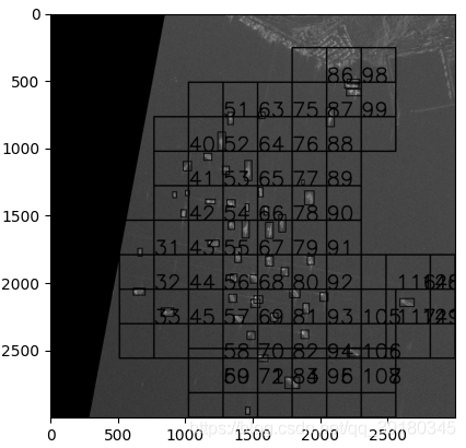
基于原图的裁剪区域的可视化结果如下:
中间有一部分代码计算了裁剪区域的中心位置,然后在中心位置写上了裁剪区域的标号,我裁剪的大小是512*512,用的步长是256,就是两个区域之间的重叠区域有256个像素宽和高,如果不展示出来这个数字就看不出来到底那个才是真正的框框。

生成的标注格式数据如下:
<annotation>
  <folder>AIR-SARShip-1.0-SUB</folder>
  <filename>SARShip-1.0-21_89-71.tiff</filename>
  <source>
    <database>AIRSAR</database>
    <resolution>3</resolution>
    <sensor>GF-3</sensor>
  </source>
  <size>
    <width>512</width>
    <height>512</height>
    <depth>1</depth>
  </size>
  <segmented>0</segmented>
  <object>
    <name>ship</name>
    <bndbox>
      <xmin>131</xmin>
      <ymin>186</ymin>
      <xmax>153</xmax>
      <ymax>223</ymax>
    </bndbox>
    <difficult>0</difficult>
  </object>
</annotation>
有写的不对的地方还望包涵哦,over
版权声明:本文为CSDN博主「MCMILer」的原创文章,遵循CC 4.0 BY-SA版权协议,转载请附上原文出处链接及本声明。
原文链接:https://blog.csdn.net/qq_39180345/article/details/115017879


